Product area |
|
| Navigation |
| Home |
| Product area |
| Automation |
| CNC |
| CNC
gallery |
| Hobby |
| CNC-Machine |
| Tutorials |
| My shop floor |
| Misc |
| Feedback |
| Contact |
| 4 AKKON CNC | |||
|
|||
1 Introduction AKKON IO control is designed for easy access
of digital and analogue inputs and outputs over USB. The hardware
can be accessed using the AKKON IO control library.
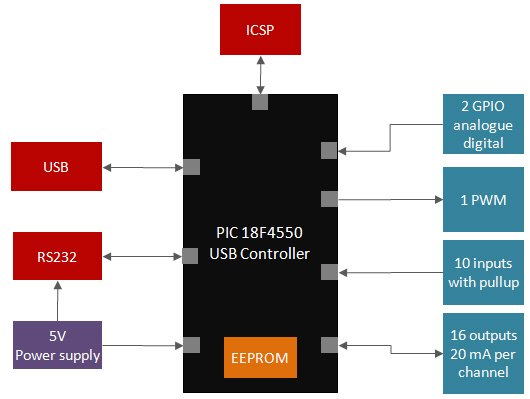
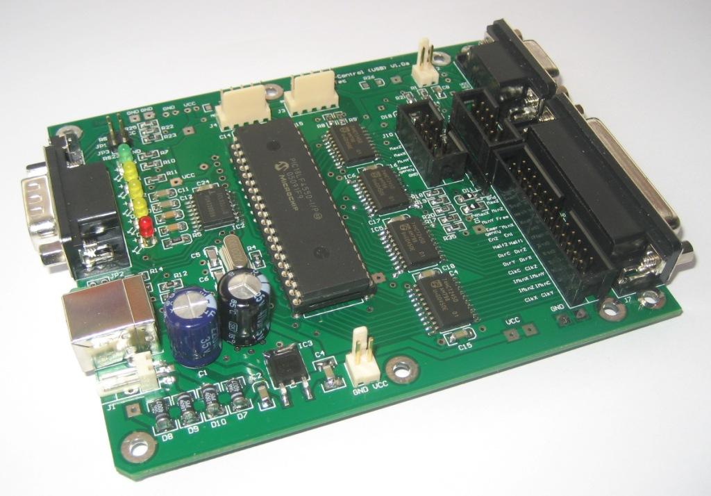
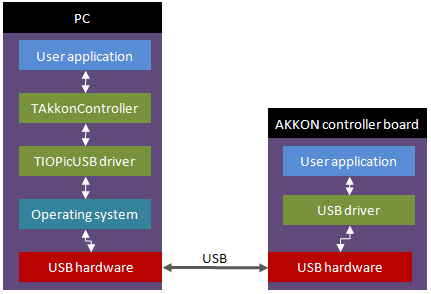
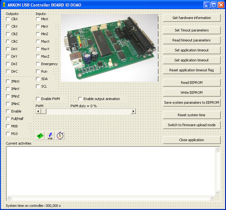
Following picture shows the AKKON controller board that will be supported by the software yet. Figure 1: AKKON Controller Board (PIC-Version) 2 Architecture of AKKON IO controllerFigure 2 shows the architecture of the AKKON IO controller.
Figure 2: Architecture of AKKON IO controller The coloured blocks show the logical units, the Arrows the direction of the information flow. A detailed description of the logical units and itus will be described in the AKKON IO controll operating manual. 3 AKKON IO control libraryUSB-programming of the AKKON IO controller programming is supported by the AKKON IO control library. The library includes the AKKON USB driver component (TIOPicUsbDriver) for basic communication and the AKKON controller component (TAkkonController) for performing IO control.
In normal case the USB driver component is not accessed directly. Moreover TIoPicUSBDriver creates an interface between the operating system and the functional logic for programming the AKKON controller board. The user application itself accesses the TAkkonController-Component and has access to different methods for steering the functional blocks on the controller. 3.1 Components3.1.1 AKKON USB driver (TIOPicUsbDriver) component The AKKON USB driver component implements basic communication
from PC to AKKON IO controller board.
In normal case the USB driver component is not accessed directly. 3.1.2 AKKON Controller (TAkkonController) component The AKKON Controller component (TAkkonController) implements methods
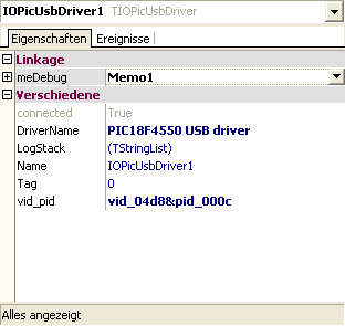
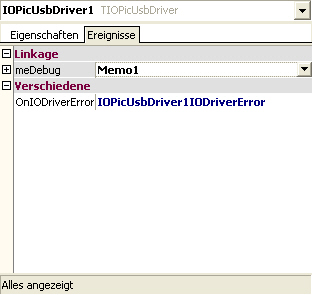
for easy access to the controller hardware. The component implements following parameters and events: 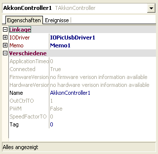 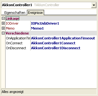 Figure 5: Parameters (left) and events supported by the TAkkonController-component Parameter IODriver holds a reference to a suitable IO driver. In the case of the AKKON IO controller board it is a reference to the TIoPicUSBdriver component. 3.2 Use of the components in the Delphi IDE
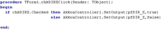
In the AKKON IO control demo application a TAkkonController, a TIoPicUsbDriver and a TTimer component is used. TAkkonController is connected with the TIoPicUsbDrvier. TTimer calls background processing of the current controller state. Following examples shows how to switch signal DIR_X logical high or low.
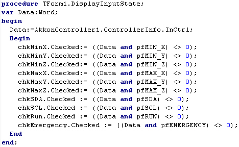
Following example demonstrates how to process information about the digital inputs. Parameter AkkonController1.ControllerInfo.InCtrl hold a 16 bit variable. Each bit of the value correspondeses to one digital input. The AKKON IO control library defines all constants (pfMIN_X, pfMIN_Y, ..) for demasking of the input state. The current controller state can be read from the controller by using a TTimer that wil be called continuously e.g. in a 250 ms interval in the background. r 4 Downloads |
 click image to enlarge
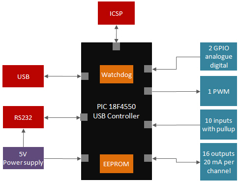
|
Version 1.0, ©Gerhard Burger 2004-2013, all rights reserved, last update 09.11.2013 |